
PLL LO N5AC and 2,3 GHz EME TRV
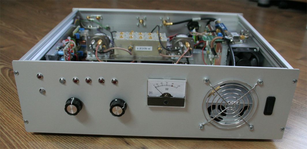
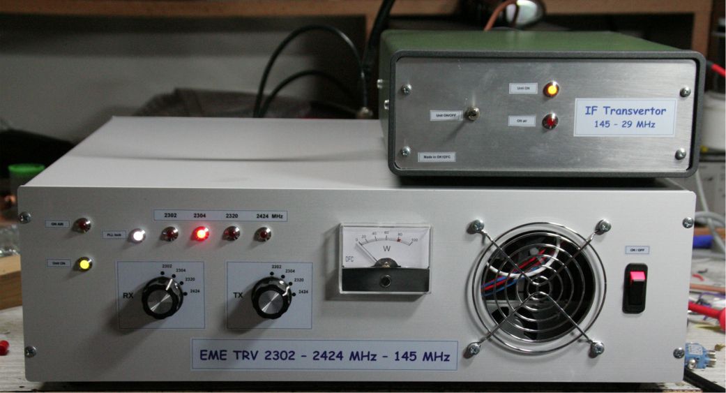
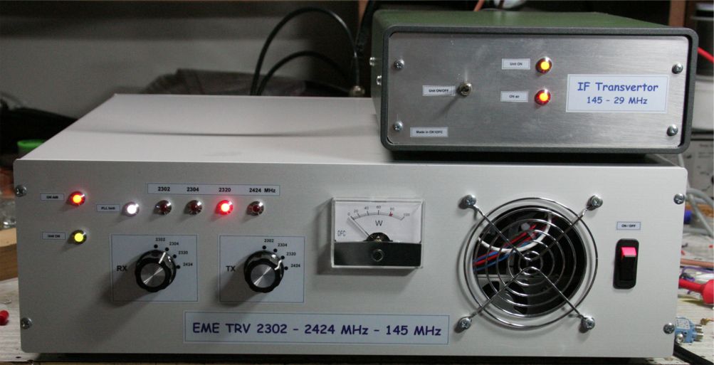
| Front panel of new EME 2302 - 2304 - 2320 - 2400 MHz TRV. Thanks to two independent RX/TX switches is possible setup also cross band between all available QRGs. Maximum output power is 80W RF what is enough for driving in to 500W SSPA. | |||
|
|||
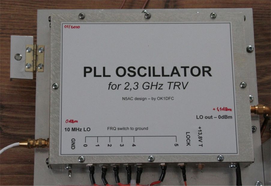
| This PLL LO is
possible to buy as a kit from N5AC
or trough Down East Microwave USA. I have choice this solution as a
perfect and simple LO for my new 2,3 GHz TRV which I am operating for EME.
Problem with switching between all available bands is presented also on
this page as a schematic and board PCB.
|
|||
| Measured LO spectrum | |||
| I am using IF 145 MHz to avoid possible interference during tropo contests. Click on thumbnail for higher resolution. | |||
| VK band | W band | EU band | JA band |
|
|
|
|
| 1,0785 GHz | 1,0795 GHz | 1,0875 GHz | 1,1395 GHz |
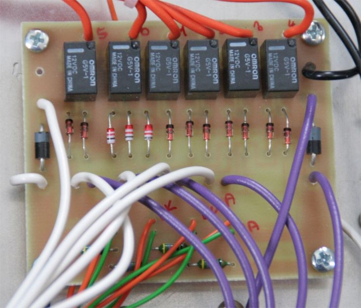
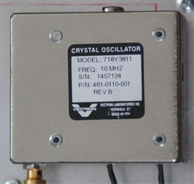
| Switching matrix for all bands spread to independent RX - TX way | Rubidium 10 MHz normal | ||
| Schematic | Parts | PCB | PDF manual |
| TRV SSPA | Power supply | TRV out | |
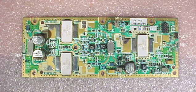
| Spectrian 80W RF out module | Internal PS for SSPA and TRV | Circulator on the TX TRV out | |
| TRV | |||
| As a base of TRV I have choice a Down East Microwave new designed 2,3 GHz TRV . Main advantage of this TRV is broadband and possibility to work on all requested frequencies 2302 VK - 2304 W - 2320 EU and 2400 JA. Other available TRVs are due to using of helix filters very narrow and does not work on those frequencies. To avoid a problem with interference by WiFi or other services, I am using switch between cavity filters instaled between VLNA and TRV also TRV and PAs in TX way. Filters are automatically switching with same matrix as used for LO. TRV also including sequencer for control all units around as a TRX, VLNA, blocking relay and internal switching of TRV. | |||
|
|||
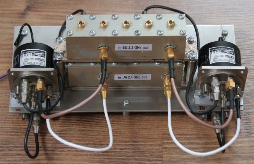
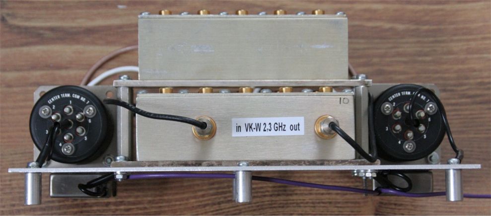
| Filters and switching bands | |||
| EU - JA filters setup | Band and RX/TX switch | VK-W filter | |
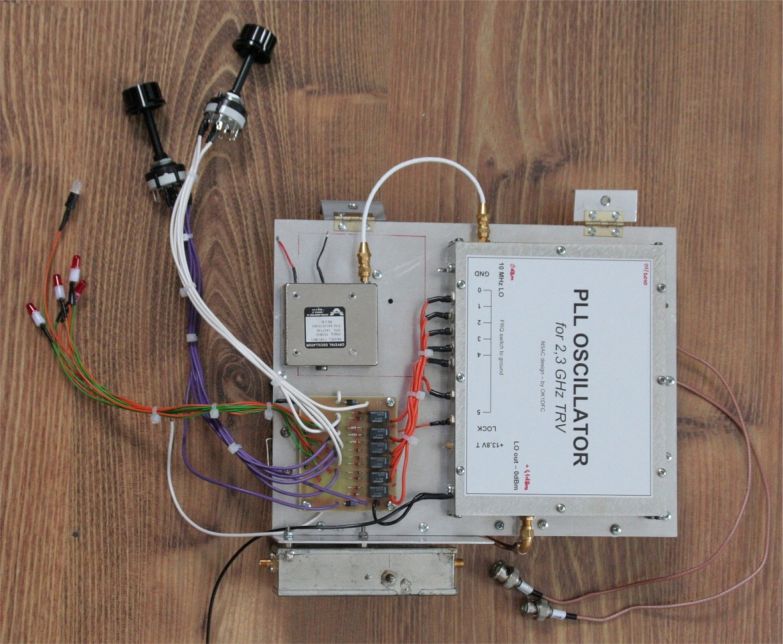
| TRV parts | |||
| TRV part top | PLL | Matrix | 10 MHz LO |
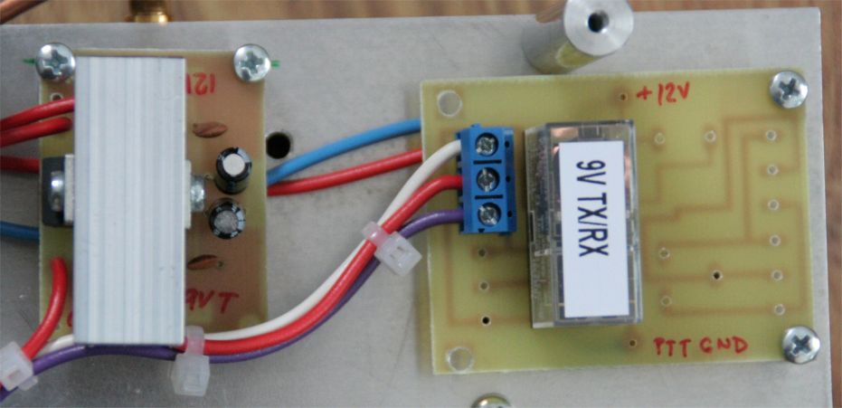
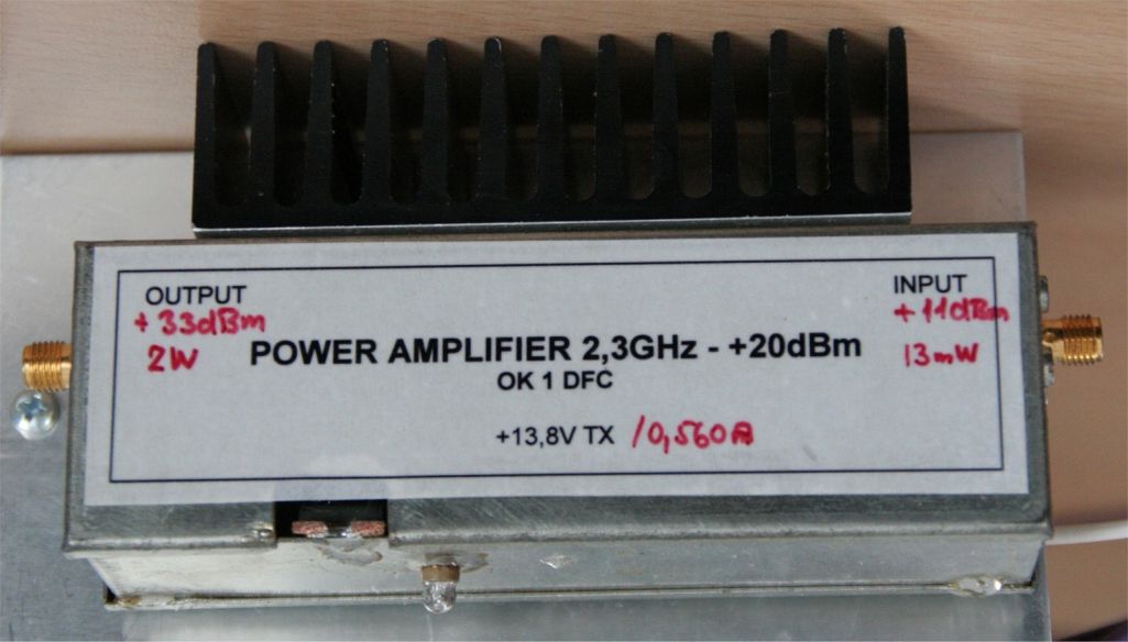
| TRV part botom | TRV | RX/TX switch and PS 12V/3A | Driver 2W |
| Sequencer | |||
|
|||
| Front panel - from left red diode top - "ON AIR" indication - green below "Unit ON" - row of diodes from left white "PLL lock" - reds "2302 - 2304 -2320 -2400 bands" - knobs below from left "RX QRG setup" - right "TX QRG setup". Indicator 100W full scale, marked 80W - air input and switch "ON/OFF" | |||
|
|||
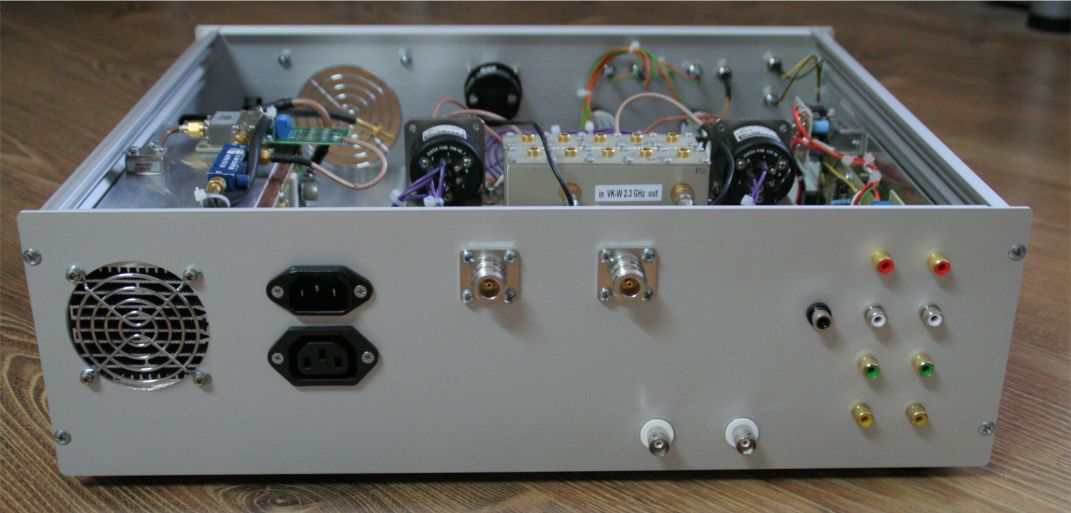
| Rear panel - from left - air output - SSPA heat sink, 230V in - 230V out for connection to IC7700 - TWO "N" - 2,3GHz TX - 2,3GHz RX - below left BNC 145 MHz IF TX - right 145 MHz IF RX - on the right side of panel outputs from SEQUENCER - from top "TRV ON" - "PA-ON" - "LNA ON" - blocking relay RX way "ON" - black Cinch connector PTT to ground. | |||
|
|||
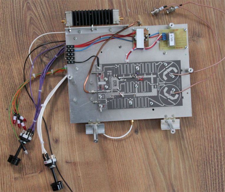
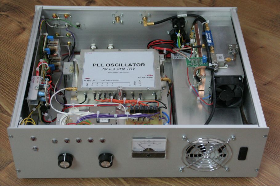
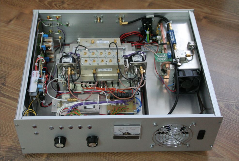
| Look into TRV without filter board, on left Sequencer, PLL and 10MHz TCXO in the middle, on right bottom Power supply 24V/20A and SSPA 80W on heat sink. | |||
|
|||
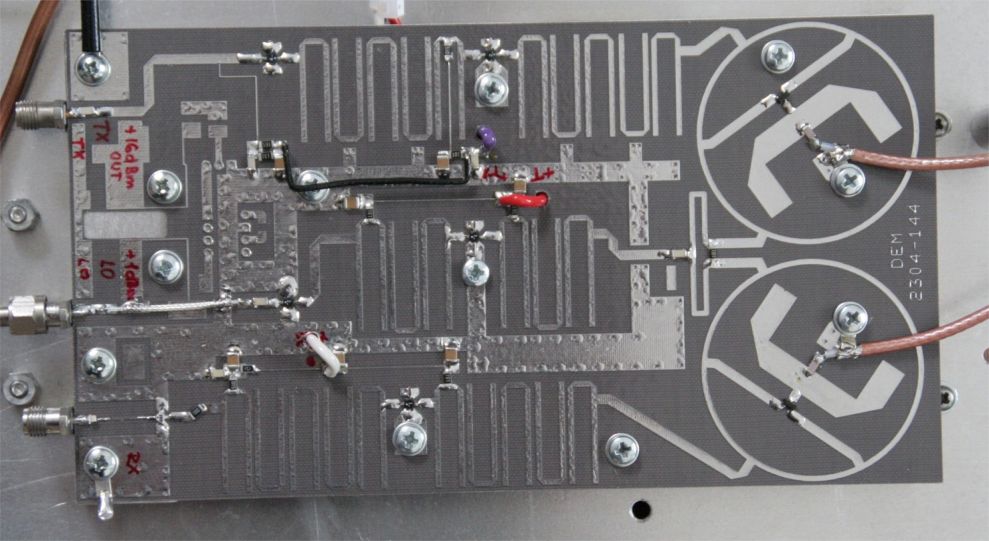
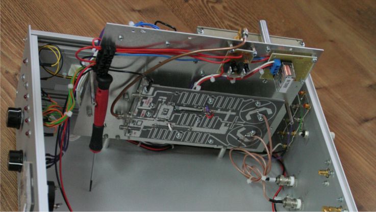
| TRV 2,3 GHz | |||
|
|||
| Look to the TRV with filter board | |||
|
|||
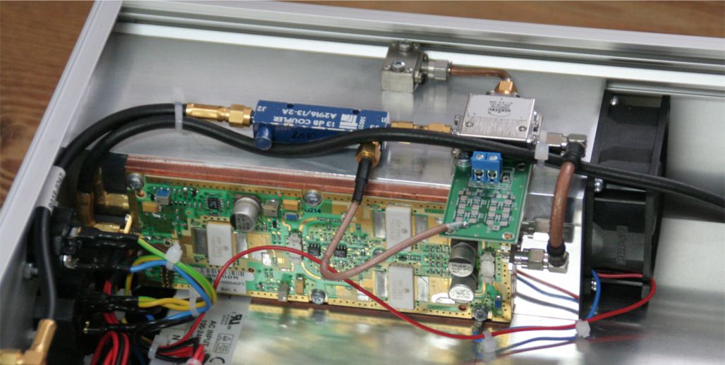
| Spectrian SSPA 80W out, circulator, directional coupler for PWR measuring with detector, heat sink with blower 24V / 4800rpm | |||
|
|||
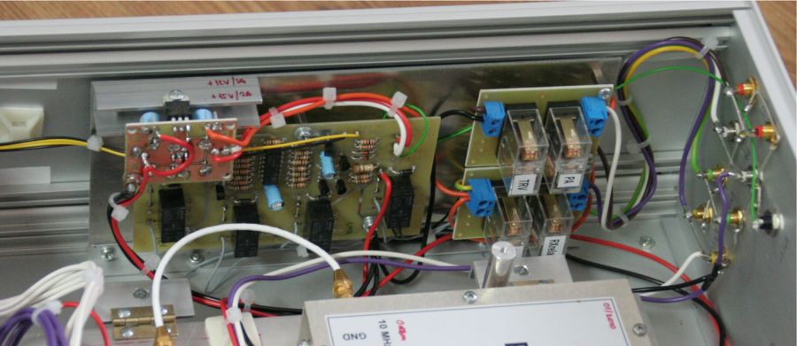
| Sequencer | |||
|
|||
| TRV in lab together with IF TRV 29/145 MHz in RX position 2304 MHz | |||
|
|||
| TRV in lab together with IF TRV 29/145 MHz in TX position 2320 MHz | |||